In predictive simulations TRANSP uses boundary conditions at a radial location set by the variable XIBOUND (for electron and ion temperature) and at XNBOUND (for the electron density)
These boundary conditions are overwritten with the pedestal location when the following switches are selected:
- MODEEDG=5
- to use boundary conditions for the electron temperature profile set by the pedestal module
- MODIEDG=5
- to use boundary conditions for the ion temperature profile set by the pedestal module
- MODNEDG=5
- to use boundary conditions for the electron density profile set by the pedestal module
NOTE: it is possible to use pedestal boundary conditions separately for the ion, electron and density profile. However, TRANSP enforces the boundary conditions for T and T to be the same. This means that, if MODEEDG=5 and MODIEDG=4, the boundary condition for T will be enforced to be at XIBOUND.
Users can impose the values of the pedestal width and height from the namelist or use a predictive model.
User-defined pedestal width
To impose the pedestal width from the namelist: NMODEL_PED_WIDTH = 0
- TEPEDW
- Electron temperature pedestal width. Positive value for physical units of cm, negative value for sqrt(ϕ/ϕ)
- TIPEDW
- Ion temperature pedestal width. Positive value for physical units of cm, negative value for sqrt(ϕ/ϕ)
- XNEPEDW
- Electron density pedestal width. Positive value for physical units of cm, negative value for sqrt(ϕ/ϕ)
User-defined pedestal height
To impose the pedestal height from the namelist: NMODEL_PED_HEIGHT = 0
- TIPED
- Ion temperature at the pedestal top [eV]. The default value is 100.0 eV
- TEPED
- Electron temperature at the pedestal top [eV]. The default value is 100.0 eV
- XNEPED
- Electron density at the pedestal top [cm]. The default value is 10
Predictive models for the pedestal pressure and width
To use a predictive model for the pedestal pressure: NMODEL_PED_HEIGHT = 1
To use a predictive model for the pedestal width: NMODEL_PED_WIDTH = 1
NOTE: the two models are not independent, since some models predict both pressure and width and results will be over-written. It is recommended to set both flags equal to 1.
When the pedestal height is predicted, the calculated density and temperature can be rescaled using the following namelist variables:
- SCALE_TEPED
- Scale factor for the electron temperature pedestal height
- SCALE_TIPED
- Scale factor for the ion temperature pedestal height
- SCALE_NEPED
- Scale factor for the electron density pedestal height
It should be noted that all pedestal models calculate the pedestal pressure, thus the pedestal temperature is derived for a given pedestal density, as (p. The resulting pedestal temperature depends on how the pedestal density is calculated.
Options to calculate the pedestal density
- LPED(2)=1
- n= 0.71 n, where n is the line averaged density. This is the original NTCC module assumption.
- LPED(2)=2
- pedestal density and width set from a fit over the density profile, according to the following parametrization:
- where:
- r is the ratio of the density at the pedestal to the central value, n = r n
- r is the ratio of the density at the separatrix to the central value, n = r n
- The fit returns the width of the pedestal in normalized poloidal flux coordinates and the value of the density at the pedestal location.
- The mid-pedestal location is taken at a pedestal half-width to the right of the pedestal. The pedestal top is defined as a pedestal half-width to the left of the pedestal location.
- LPED(2)=3
- n= C n, where C is set with the namelist variable CPED(4).
- LPED(2)=4
- pedestal density and width set at the location of the maximum profile gradient.

Important: the output values NEPED and NEPEDW represent the values at the pedestal top, which is used in TRANSP as a boundary conditions for the core transport predictions.
Options to calculate the pedestal pressure
Original NTCC model options:
The description of the NTCC PEDESTAL module can be found here and the standalone code can be downloaded from the NTCC directory.
The models included in the NTCC module are described in the paper by T. Onjun et al, Phys. Plasmas 9 (2011) 5018
- LPED(3)=1
- Pedestal model using the pedestal width based on magnetic and flow shear stabilization (see section 3.1 in this pdf document for detailed information).
- LPED(3)=2
- Pedestal model using the pedestal widhth based on flow shear stabilization (see section 3.2 in this pdf document for detailed information)
- LPED(3)=3
- Pedestal temperature model using the pedestal width based on normalized pressure (see section 3.3 in this pdf document for detailed information)
- LPED(3)=11
- Pedestal temperature model based on thermal conduction model I (see section 3.4 in this pdf document for detailed information)
- LPED(3)=12
- Pedestal temperature model based on thermal conduction model II (see section 3.5 in this pdf document for detailed information)
- LPED(3)=21
- This model needs the pedestal width in cm as an input, using CPED(3). Alternatively, the pedestal width can be taken from a fit over the pedestal density, when the density profile is prescribed with UFILE. In this case set CPED(3)=0.0 and LPED(2)=2
- NOTE: this parametrization has been derived for ITER, do not use otherwise.
- LPED(3)=22
- This model needs the pedestal width in cm as an input, using CPED(3). Alternatively, the pedestal width can be taken from a fit over the pedestal density, when the density profile is prescribed with UFILE. In this case set CPED(3)=0.0 and LPED(2)=2
- NOTE: this parametrization has been derived for ITER, do not use otherwise.
- LPED(3)=213
- This model combines the option LPED(3)=3 for the calculation of the pedestal width and LPED(3)=21 for the calculation of the height. In this case, even when LPED(2)=2 is selected, the pedestal width is calculated from the NTCC model. There is no need for specifying the value of CPED(3) with this option.
- NOTE: this model uses a parametrization that has been derived for ITER, do not use otherwise.
- LPED(3)=223
- This model combines the option LPED(3)=3 for the calculation of the pedestal width and LPED(3)=21 for the calculation of the height. In this case, even when LPED(2)=2 is selected, the pedestal width is calculated from the NTCC model. There is no need for specifying the value of CPED(3) with this option.
- NOTE: this model uses a parametrization that has been derived for ITER, do not use otherwise.
- LPED(3)=23
- LPED(3)=100
- This model uses a multi-dimension interpolation over the space of parameters that are input to the EPED1 calculations [P. Snyder et al, Nucl. Fusion 51 (2011) 103016]. The lookup table consists of over 6000 EPED1 calculations that cover the operational parameter space of ITER and that are described here.
- NOTE: this lookup table has been derived for ITER, do not use otherwise.
- LPED(3)=111
- Neural network based on EPED1 calculations, trained over calculations for ITER, DIII-D, C-Mod, JET and KSTAR [O. Meneghini et al, Nucl. Fusion 57 (2017) 086034].
Models based on MHD stability calculations
These options are based on the work by P. Maget et al, NF 53 (2013) 093011:
Models based on EPED1
Tanh fit reconstruction of the pedestal
- LPED(9)=1
- An option has been implemented to reconstruct a pedestal shape from a tanh function (see equation above for the density profile). This option is activated by setting LPED(9)=1. For backward compatibility this option is not available for the NTCC module, which uses a linear profile between the pedestal and the plasma boundary.
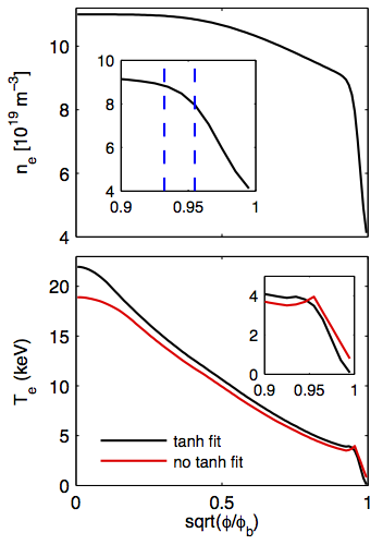
|
Top: Analytic density profile; the inset shows the position of the pedestal and the pedestal top. |